2.4 - Boolean Logic
Logic Diagrams
- Boolean logic diagrams are a graphical representation of the Boolean
logic used in programming.
- Boolean logic is a branching system that uses only two values: true and
false.
- They are used to test the logic of a program, and to debug the program.
- There are two types of Boolean logic diagrams: truth tables and logic gates.
- A truth table is a table that shows all possible combinations of inputs
and their corresponding outputs.
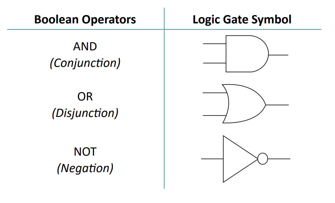
- A logic gate is a diagram that shows logic being performed: things like
AND, OR and NOT.
Logic gates
- There are three main types of logic gates: AND, OR, and NOT.
- AND is a gate that performs an AND operation, meaning that both inputs
must be true for the output to be true.
- OR is a gate that performs an OR operation, meaning that at least one input
must be true for the output to be true.
- NOT is a gate that performs a NOT operation, meaning that the input is
inverted, so if the input is true, the output is false, and vice versa.

- You may also see V as OR, ∧ as AND and ¬ as NOT.
Truth tables
- A truth table is a table that shows all possible combinations of
inputs and their corresponding outputs.
- The first row of the table shows the inputs, the second row shows the corresponding
outputs, and the third row shows the logic gate.
| AND | OR | NOT | |||||
|---|---|---|---|---|---|---|---|
| A | B | A AND B | A | B | A OR B | A | NOT A |
| 0 | 0 | 0 | 0 | 0 | 0 | 0 | 1 |
| 0 | 1 | 0 | 0 | 1 | 1 | 1 | 0 |
| 1 | 0 | 0 | 1 | 0 | 1 | 1 | 0 |
| 1 | 1 | 1 | 1 | 1 | 1 | 1 | 0 |
Combined Operators
- Boolean operators can be combined to create more complex expressions.
- You do not need to know these operators, but you do need to know how to combine
them and as such it's a lot easier if you know some of them.
- Types of combined operators are XOR (exclusive or), NAND (not and), and
NOR (not or).
- XOR is a gate that performs an exclusive or operation, meaning that only
one of the inputs must be true for the output to be true.
- NAND is a gate that performs a not and operation, meaning that both inputs
must be false for the output to be true.
- NOR is a gate that performs a not or operation, meaning that at least one
input must be false for the output to be true.
Truth tables
XOR
| INPUT | OUTPUT | |
|---|---|---|
| A | B | A XOR B |
| 0 | 0 | 0 |
| 0 | 1 | 1 |
| 1 | 0 | 1 |
| 1 | 1 | 0 |
NOR
| INPUT | OUTPUT | |
|---|---|---|
| A | B | A NOR B |
| 0 | 0 | 1 |
| 0 | 1 | 0 |
| 1 | 0 | 0 |
| 1 | 1 | 0 |
NAND
| INPUT | OUTPUT | |
|---|---|---|
| A | B | A NAND B |
| 0 | 0 | 1 |
| 0 | 1 | 1 |
| 1 | 0 | 1 |
| 1 | 1 | 0 |
Combined Gates

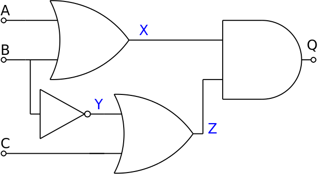
- In this diagram, A, B and C are inputs, X is the output
of the first OR, Y of the first NOT, Z of the second OR,
and Q of the whole thing.
- The whole thing is Q = (A OR B) AND ((NOT B) OR C)
